What Is the Mechanism Behind a Butterfly Valve's Operation? | GEKO Valve
Sep 21, 2026
What Is the Mechanism Behind a Butterfly Valve's Operation?
Butterfly valves are one of the most versatile quarter-turn control valves used in modern industrial and municipal piping systems. While most engineers are familiar with the fast switching and compact structure of industrial butterfly valves, many do not fully understand the complete mechanical operation mechanism that enables reliable fluid isolation, pressure resistance, and precise flow modulation for different butterfly valve products. Unlike ball valves that rely on spherical ball sealing or gate valves with vertical stroke movement, butterfly valves adopt a unique rotary disc mechanical structure. This article deeply analyzes the full mechanical operating mechanism of butterfly valves, including torque transmission, disc movement logic, sealing mechanics of soft seated and metal seated butterfly valves, offset working principles, and actuator coordination for automated butterfly valves.
1. Overall Mechanical Operation Mechanism Overview
The entire operation mechanism of a butterfly valve is based on rotary mechanical transmission and fluid dynamic matching. The actuator outputs rotational torque, which is transmitted through the valve stem to drive the internal butterfly disc to perform 90-degree quarter-turn rotation. By changing the angle of the disc inside the pipeline bore, the valve changes the flow cross-sectional area, thereby realizing three core mechanical functions: fluid cut-off, full flow passage, and intermediate throttling regulation. The whole mechanical structure features fewer transmission parts, simpler motion logic, and faster response than multi-stroke industrial valves.
2. Core Mechanical Transmission Mechanism
Torque transmission is the core power source for butterfly valve operation. The complete mechanical transmission chain consists of an actuator, valve stem, shaft pin, and butterfly disc, achieving accurate power conversion and motion output.
When the actuator receives an opening or closing signal, it generates rotational torque and transmits it to the vertical valve stem. The valve stem is fixed with the butterfly disc through precision shaft pins, eliminating idle rotation and ensuring synchronous angle movement. The stem shaft relies on high-precision shaft sleeves and sealing packing to reduce friction resistance, ensuring flexible and stable rotation without jamming. This mechanical transmission mechanism converts electrical, pneumatic, or manual power into mechanical rotation, completing valve opening and closing actions efficiently.
3. Disc Flow Control Mechanical Mechanism
The butterfly disc is the executive component of fluid control, and its angular displacement directly determines the pipeline flow state. Different opening angles correspond to completely different mechanical flow control states.
At a 0-degree closed position, the disc is completely perpendicular to the fluid direction, forming a full barrier against the medium. Under the action of medium pressure, the disc fits tightly with the valve seat to achieve mechanical compression sealing. At a 90-degree fully open position, the disc is parallel to the fluid direction, minimizing flow resistance and allowing maximum fluid passage. At any angle between 0 and 90 degrees, the disc forms an overlapping throttling structure with the pipeline bore, using mechanical occlusion to change flow velocity and pressure, realizing continuous flow regulation.
4. Sealing Mechanical Mechanism (Soft Seal & Hard Seal)
The reliable shutoff performance of butterfly valves comes from two different mechanical sealing mechanisms, applicable to different industrial working conditions:
4.1 Elastic Compression Sealing Mechanism (Soft Seat)
Soft seated butterfly valves use elastic polymer seats such as EPDM and Viton. During the closing stroke, the disc mechanically squeezes the elastic seat to produce micro elastic deformation. The deformed seat fills the tiny mechanical gaps between the disc edge and the valve body, achieving zero-leakage sealing. This elastic compensation mechanical mechanism adapts to minor machining tolerances and pipeline pressure changes, ensuring tight shutoff of soft seated butterfly valves under normal temperature and low-pressure conditions.
4.2 Precision Mechanical Lapping Sealing Mechanism (Metal Seat)
Metal seated butterfly valves adopt a rigid metal-to-metal sealing mechanism. After precision machining and mirror lapping, the disc and seat form a high-precision matching sealing pair. Relying on mechanical rigid contact and medium pressure self-tightening force, the valve realizes stable sealing under high-temperature, high-pressure, and abrasive working conditions. This mechanical sealing structure has no aging deformation problem and supports long-term high-cycle industrial operation of heavy duty butterfly valves.
5. Offset Butterfly Valve Zero-Friction Mechanical Mechanism
Concentric and offset butterfly valves have fundamental differences in mechanical operation logic, which determines service life and pressure resistance performance.
Concentric butterfly valves feature a completely coincident center of stem, disc, and pipeline. The disc keeps continuous mechanical friction with the seat during each opening and closing cycle, leading to easy seat wear. In contrast, triple offset butterfly valves and double offset butterfly valves adopt a spatial offset mechanical structure. At the initial rotation stage, the disc automatically separates from the sealing seat without friction contact. Only at the final closing angle does the disc contact the seat for positioning and sealing. This zero-friction mechanical operation mechanism greatly reduces component wear, improves valve durability, and adapts to heavy-duty frequent switching working conditions for offset butterfly valve products.
6. Automated Coordination Mechanism of Actuators
Different actuators form different automatic operation mechanisms, matching modern intelligent pipeline systems:
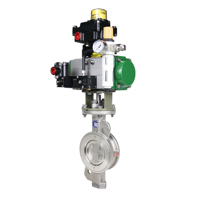
Pneumatic Butterfly Valve Mechanism: Converts compressed air pressure energy into mechanical rotation torque, featuring fast action and explosion-proof mechanical performance, suitable for hazardous industrial environments.
Electric Butterfly Valve Mechanism: Uses motor drive and reducer torque amplification to achieve precise angle positioning, supporting remote signal control and proportional regulation.
Manual Butterfly Valve Mechanism: Relies on manual mechanical torque input, simple transmission structure, stable and reliable for low-frequency operation.
7. Industrial Advantages of Butterfly Valve Mechanical Mechanism
The unique mechanical operation structure endows industrial butterfly valves with irreplaceable industrial advantages: compact mechanical layout saves installation space for wafer and lug butterfly valves, simple transmission structure reduces failure rates, zero-friction offset mechanism extends the service life of triple offset butterfly valves, and flexible angular displacement realizes dual functions of isolation and throttling for modulating butterfly valves. These mechanical characteristics make various types of butterfly valves the preferred solution for large-diameter industrial and municipal fluid control systems.
8. GEKO Valve High-Precision Mechanical Design
GEKO Valve optimizes the internal mechanical operation mechanism of all industrial butterfly valves. Adopting precision casting, CNC machining and mirror lapping technology, our wafer butterfly valves, lug butterfly valves, metal seated and soft seated butterfly valves feature uniform torque transmission, flexible rotation, precise disc positioning and stable sealing performance. Complete product series including concentric, double offset and triple offset butterfly valves fully meet the mechanical operation requirements of different low, medium and high-pressure industrial pipelines.
9 Core SEO Keywords: Industrial Butterfly Valve, Triple Offset Butterfly Valve, Soft Seated Butterfly Valve, Metal Seated Butterfly Valve, Wafer Butterfly Valve, Lug Butterfly Valve, Modulating Butterfly Valve, Heavy Duty Butterfly Valve, Automated Butterfly Valve
EN SAVOIR PLUS






 E-mail
: info@geko-union.com
E-mail
: info@geko-union.com
 E-mail
: info@geko-valves.de
E-mail
: info@geko-valves.de
 E-mail
: tw@geko-union.com
E-mail
: tw@geko-union.com
 E-mail
: nl@geko-union.com
E-mail
: nl@geko-union.com



 Réseau IPv6 pris en charge